How ESP engineers maintain a high level of equipment performance and reliability!
WHY WE USE CONDITION MONITORING
The application of engineering tools provides:
- Adequate warning of imminent or potential critical failures
- The condition of the equipment and stores valuable data for analysis
- The opportunity to prioritise maintenance and repairs, therefore optimising resources
- The opportunity to minimise downtime and therefore minimise disruption to a critical facility or sectors of the facility.
WHAT IS CONDITION MONITORING?
Condition Monitoring (CM) is the process used to determine the operational state and health of a machine for the purpose of detecting potential failures before they turn into functional or critical failures.
The CM process consists of periodical or continuous data collection, data analysis, interpretation and diagnosis.
Condition Monitoring is an integral part of an establishments Complex Sensitive Predictive Maintenance (PM): which is a widely used maintenance philosophy (this is also known as
Condition-Based Maintenance) - CBM and is prominent in the likes of very specialised, complex and sensitive establishments such as hospitals.).
This philosophy is based on scheduling maintenance activities only when a possible functional failure is detected. CBM enhances operational effectiveness and safety through research and development of technologies to accurately and reliably predict the remaining useful life of in-service equipment.
CM optimizes equipment readiness while reducing maintenance and staffing requirements.
Typical CM includes the following analysing techniques:
- Vibration
- Oil analysis
- Wear particle
- Ultrasonic
- Thermographic
- Motor current signature the detection of friction,
- The ionization process,
- Identification of turbulence “cavitation”
Remember: all of these tools provide very valuable information which can be used to evaluate the performance of the equipment.
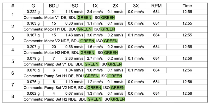
EXAMPLE OF REPORT
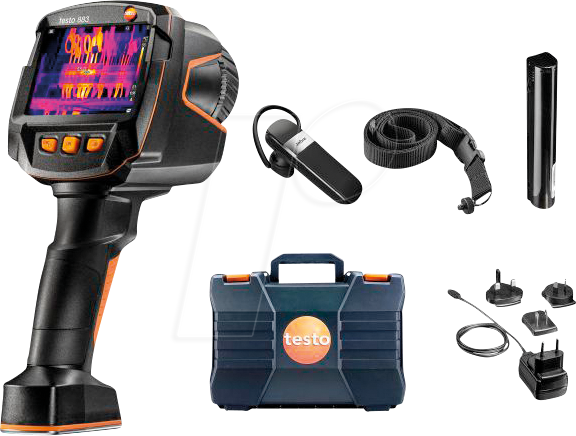
THE THERMAL IMAGE CAMERA
This specialised test equipment gives a very safe way to monitor the condition of the equipment and provides a non-contact and non-evasive inspection method
By using the camera, the experienced user can quickly identify condition of mechanical and electrical equipment in its operational state.
With experience, many fault conditions can be quickly identified.
This image is showing a current overload on one of the phases using our Thermo-graphic camera.
This image shows overcurrent through the phase connection on the right, which is glowing very brightly.
With the use of Rotational Alignment, ultrasound, thermography, vibration analysis and endoscopes, you will find that these are essential for the predictability of failure and the currently maintained equipment’s condition.


Normal Facilities HVAC PPM Conception (First Responders not trained properly in specialised equipment).
- They would have checked the equipment
- They would have looked, listened and smelt, and to untrained personnel first instinct indicates that everything seems ok
The client and their users of a specialised facility should not be exposed to risk! With the use of new technology, which ESP are proud to have, it may show us something very different. The use of ultrasound, thermography, vibration analysis and endoscopes will find problematic equipment information rapidly, giving an insight to its true working condition and zeroing in on the affected component/s giving us strong directive in what’s wrong and what can be done to fix it properly and in a timely manner.
INSPECTIONS: A QUICK OVERVIEW
- Can be used to identify components or conditions which can generate heat Example: In the electrical world, the user can identify the following fault conditions, Corona, arcing, partial discharge or tracking, overload and overcurrent conditions
- Mechanical vibrations Pumps, AHU's, Chillers etc....
- Condition of the generating and voltage transformation equipment
- Condition of the establishments control equipment, insulators, relays and contactors
- When electrical systems such as switchgear, and transformers fail the results can be catastrophic, especially on the power transmission and distribution side. If these conditions are left undetected, they can become a source of an arc flash incident which could result in a major health and safety incident.
We have used our equipment on numerous occasions to identify steam distribution networks and on other equipment, finding:
- System leaks
- Vacuum leaks
- Pipework, valves or steam traps
- Compressed air or gases
- Combustion chambers and insulation breakdowns
Below is a list of testing that will benefit the user and end user, i.e. the Engineering Department is confident the plant is functioning at an optimum levels.
GOOD QUALITY MAINTENANCE AND REPAIR KEEPS PLANT ROOMS SAFE AND RELIABLE
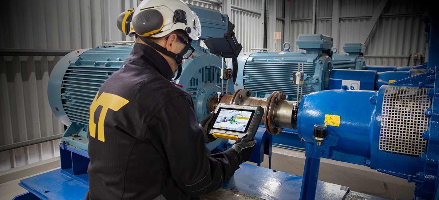
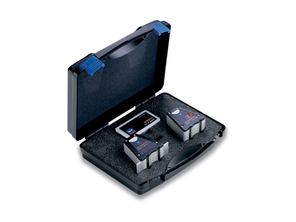
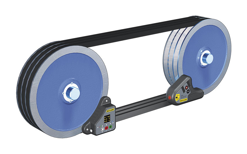
An advanced laser alignment solution for achieving accurate shaft alignments
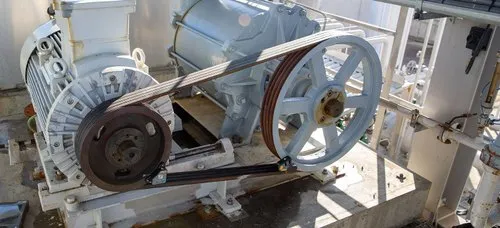
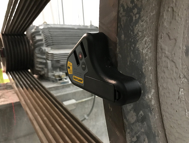
SKF TMEB2 belt alignment -EASILASER belt alignment.
You reduce the wear on sheaves/pulleys, belts, bearings and seals, and you also get lower noise and vibration levels. The accuracy of the digital readout means that you can align within prescribed tolerances and rely on the result. Especially transmissions with two or more belts, or wide belts, are highly affected by misalignment, causing large differences in belt tensions and also increased wear and tear on edges.
Misalignment can also attribute to premature bearing failure and Pulley wear. We also use belt tension gauges, both physical and Harmonic for maintaining correct manufacturers transmission requirements.
This equipment will provide the user a real time picture of the condition of the equipment under their supervision.
Also quickly identifies any potential fault conditions which may need instant attention or potential rescheduling of preventative maintenance.
The 1st image shows an Endoscope video and Optical tools. These are used for internal inspections of machines or equipment where the zone you want to look at is difficult to get to.
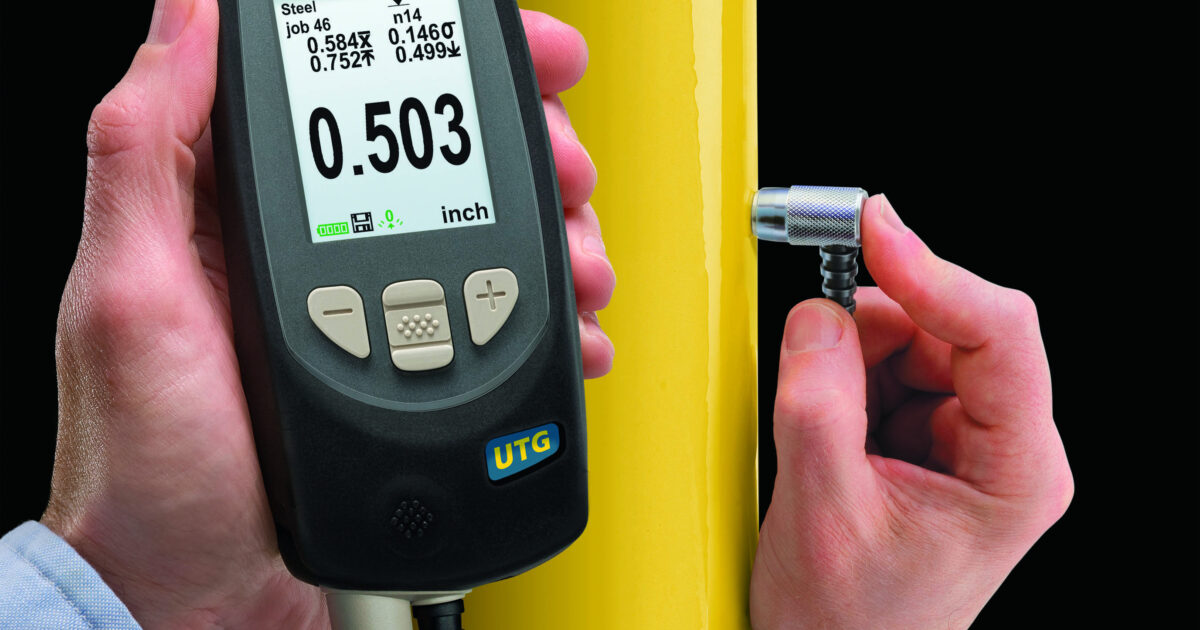
Below, our Ultrasonic Pipe Thickness Gauge. determines an internal pipes condition.
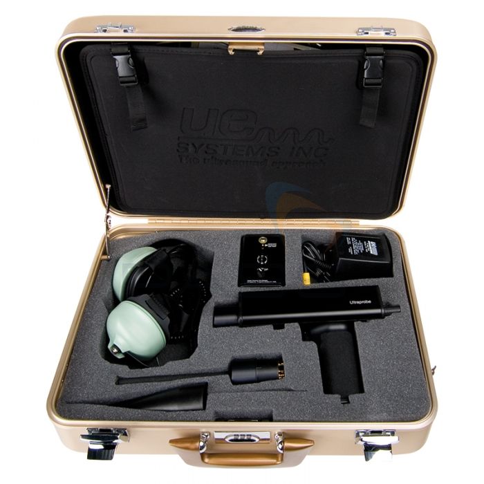
The image shows UE Systems Ultrasonic leak detection gun, using the Ultra probe 9000
The application of this test equipment is ideal for quickly finding compressed air leaks and refrigerant system leaks, at pipe work joints, identifying bearing failures, and ensuring correct greasing routines are being followed.
